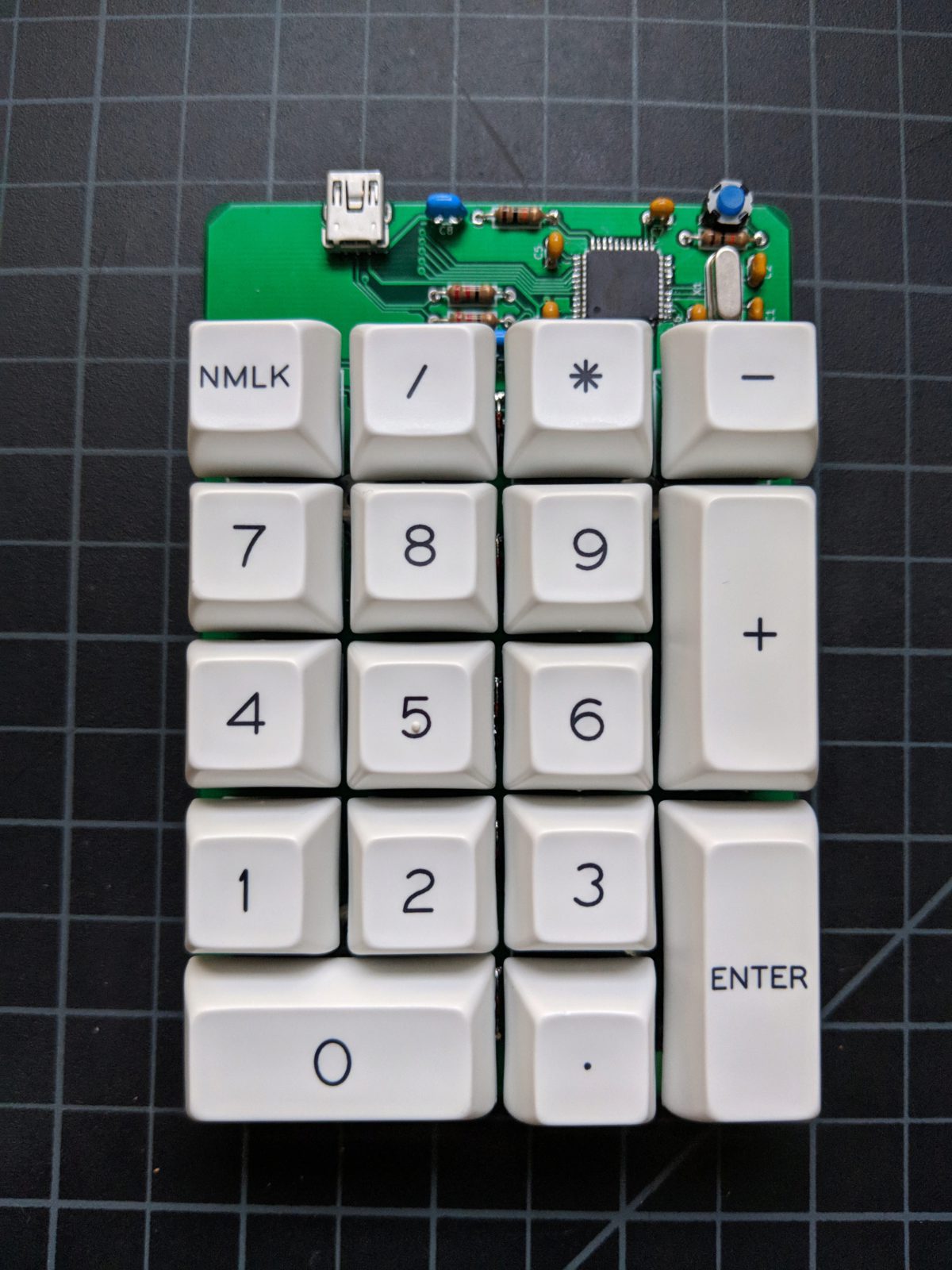
naKey Numpad Build Guide
A keyboard with all through-hole components except the chip!
naKey what?
Pronounced nah-key. This keyboard is best enjoyed raw without a case. Designed for its PCB aesthetic and its ability to more easily introduce the components on a printed circuit board. The only surface mounted part is the Atmega32u4 (if you take one of our workshops, this chip will come pre-soldered). All other components are through-hole. We chose to do this for aesthetics (through-hole so pretty), beginner-friendly soldering, and easier component identification.
Bill of Materials
- naKey PCB
- Atmega32u4 (pre-soldered if from cKeys)
- Mini USB port
- 16 MHz Crystal
- Reset Switch
- Diodes x 17
- 22 Ohm Resistors x 2
- 10k Ohm Resistors x 2
- 1 uf Capacitors x 2
- 27uF Crystal Capacitors x 2
- 0.1uF Decoupling Capacitors x 4
- 2u Stabilizers x 3
- Rubber Bumpons x 4
Kit-less and sourcing parts yourself? Here is an Octopart BOM for your convenience.
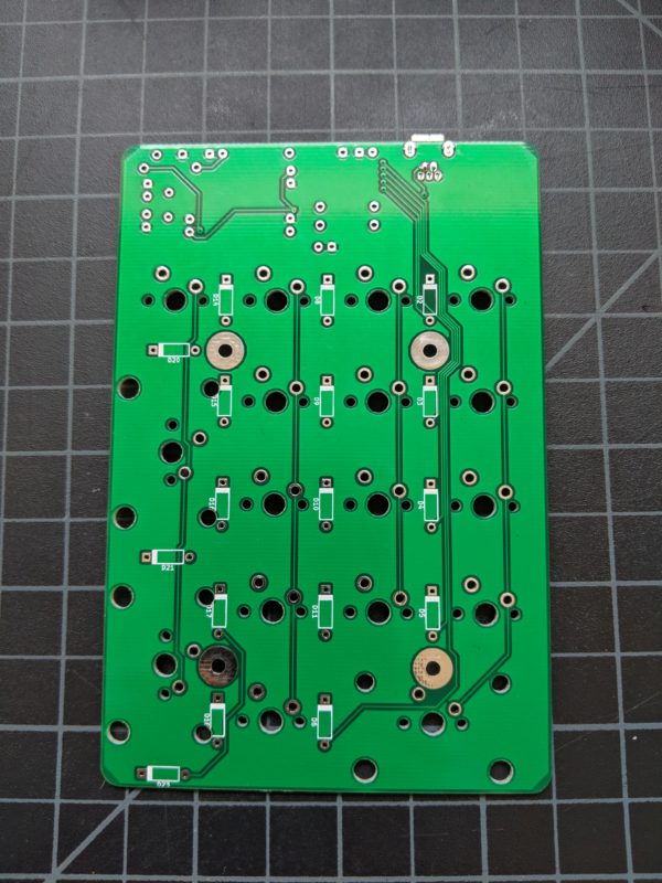
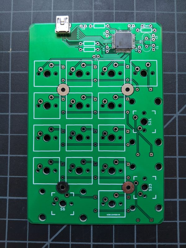
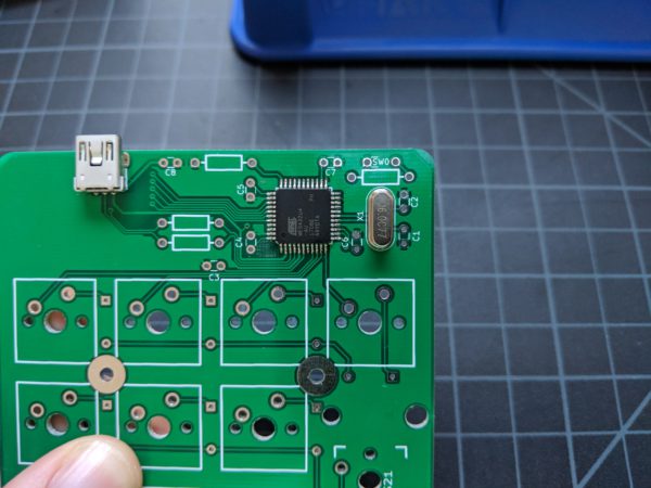
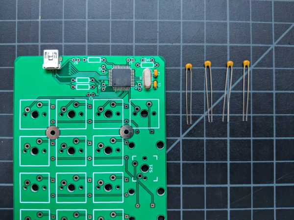
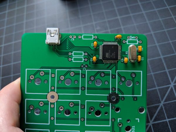
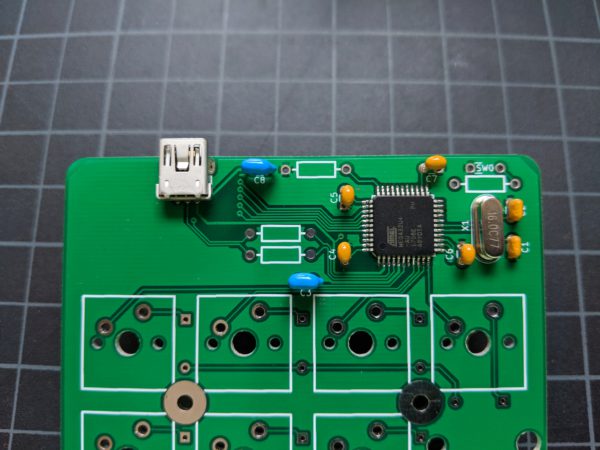
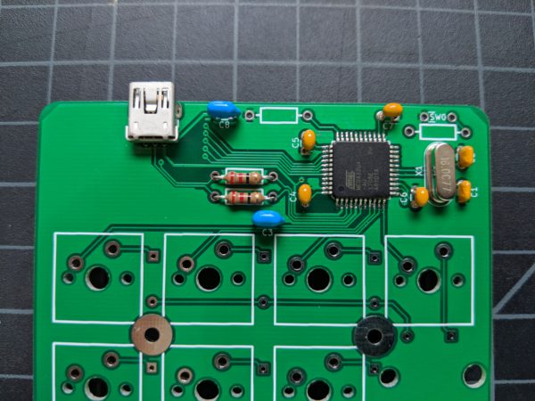
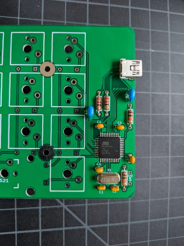
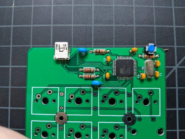
Step 1: Get to know your PCB
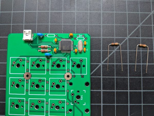
Step 2: Solder crystal
This is the heartbeat of your keyboard in as much as your heartbeat sets your body's BPM. But the analogy falls apart quickly. The crystal produces a precise 16mhz frequency which provides a stable clock signal for the Atmega32u4. Think of the quartz in vintage watches that maintain accurate time. This crystal keeps time for your keyboard.
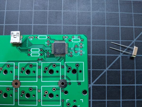
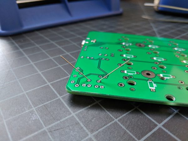
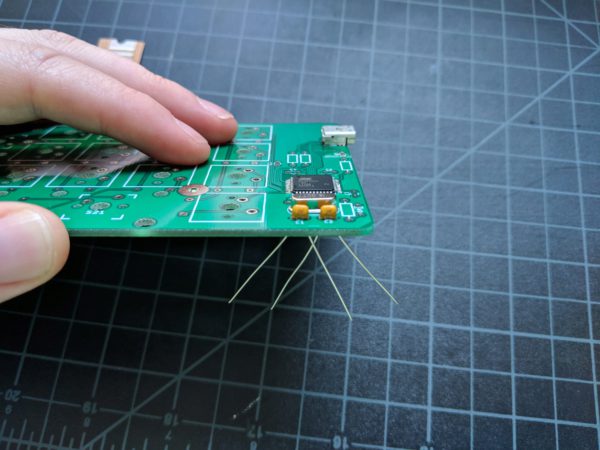
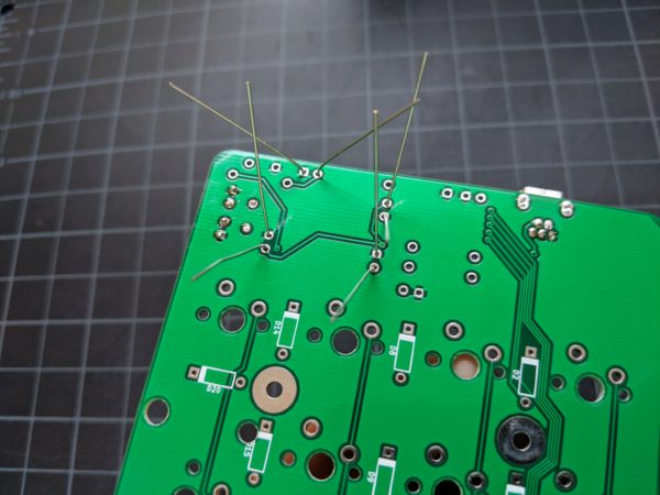
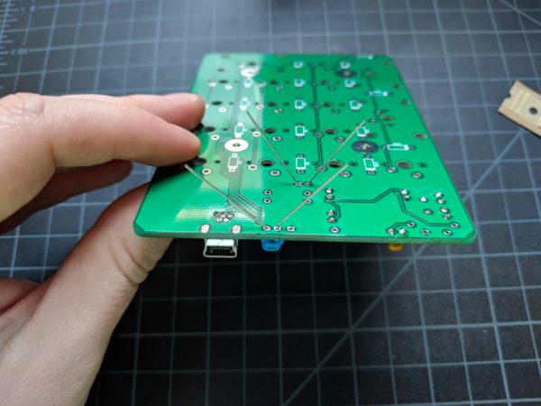
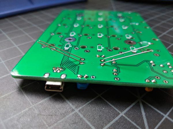
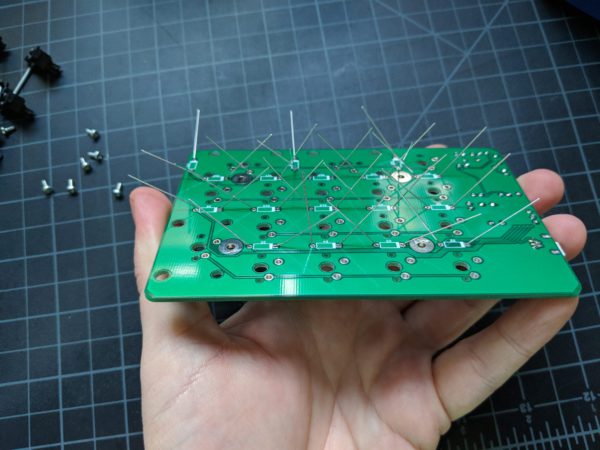
Place the crystal's pins through the top of the PCB. Your crystal does not have specific polarity; stick either pin in either hole. Then flip the PCB over while holding the crystal in place.
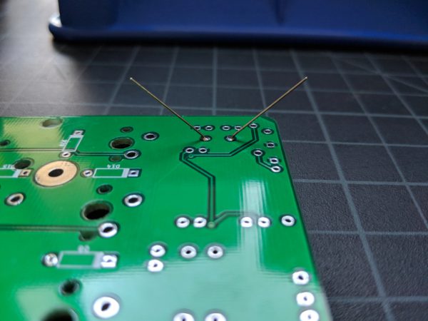
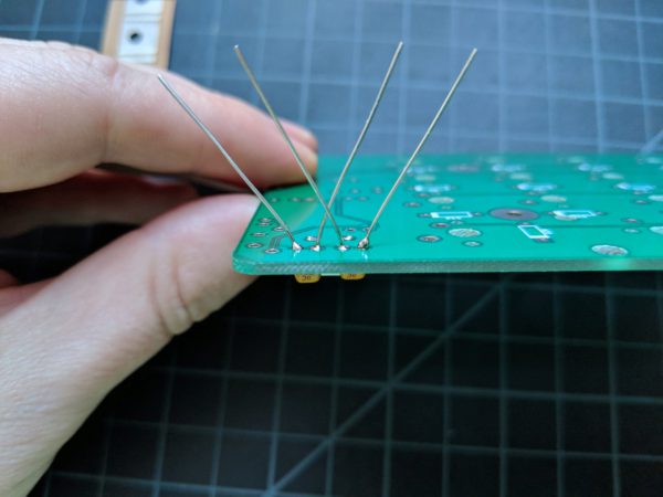
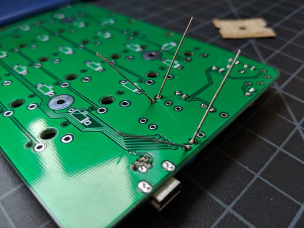
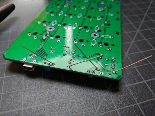
In the image below, the pins are bent outward to hold the crystal in place once flipped over. Alternatively, if you prefer not to bend your pins, you can use masking or painter's tape to hold the crystal in place.
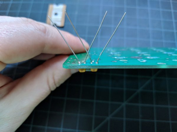
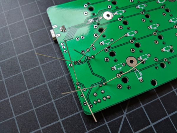
Solder the crystal's pins to the PCB and then clip the excess length of the pins.
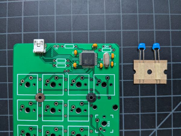
Step 3: Solder 27uF crystal capacitors
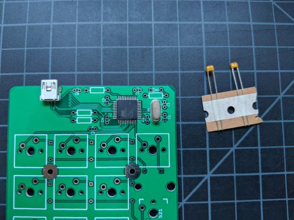
These are your crystal load capacitors.
The image on the left shows an example of a blob of solder. Blob bad! In order to fix this, the solder was reheated by the soldering iron and re-flowed. The right image shows the result.
Step 4: Solder 0.1uF capacitors
Step 5: Solder 1uf capacitors
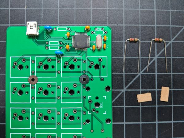
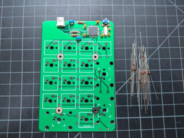
Step 6: Solder 22 ohm resistors
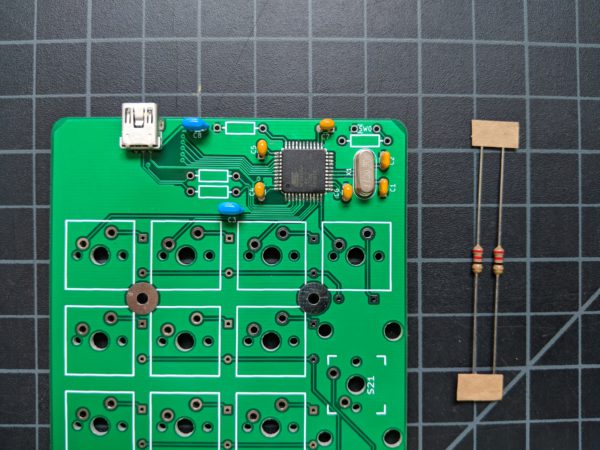
Unlike the diodes that you will solder in step 9, resistors are not directional. The wires can be inserted in either direction.
The way to identify a resistor is by the color code; those little strips of color mean something. When first learning to read resistor color codes, you might find it difficult to differentiate certain colors. And different manufacturer's colors will not always match. The color code for your 22 ohm resistors is red-red-black-gold.
Step 7: Solder 10k ohm resistors
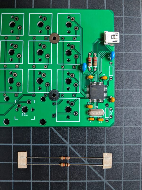
Resistor color code: brown-black-orange-gold
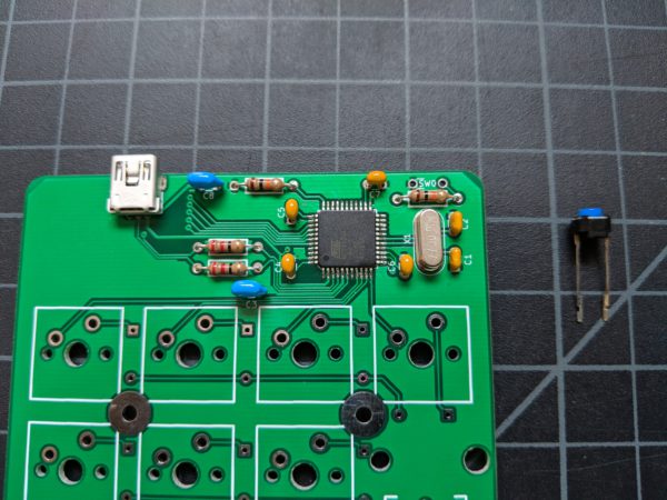
Step 8: Solder reset switch
Step 9: Solder diodes
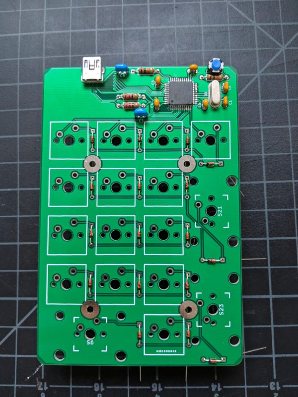
Important: Diodes are directional. If you solder them in the incorrect direction, your keyboard will not work as expected.
Pre-bend all of your diodes so that the ends of the wires fit smoothly into the PCB holes.
Locate the black line on a diode. The wire coming from this end goes into the circle-marked hole of the PCB. The wire on the other end goes through the square-marked hole. Make certain the glass section of the diode sits flush against the PCB. Solder both ends.
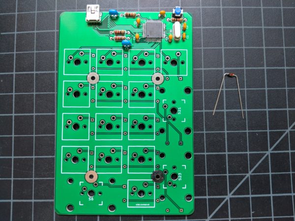
Step 10: Connect stabilizers
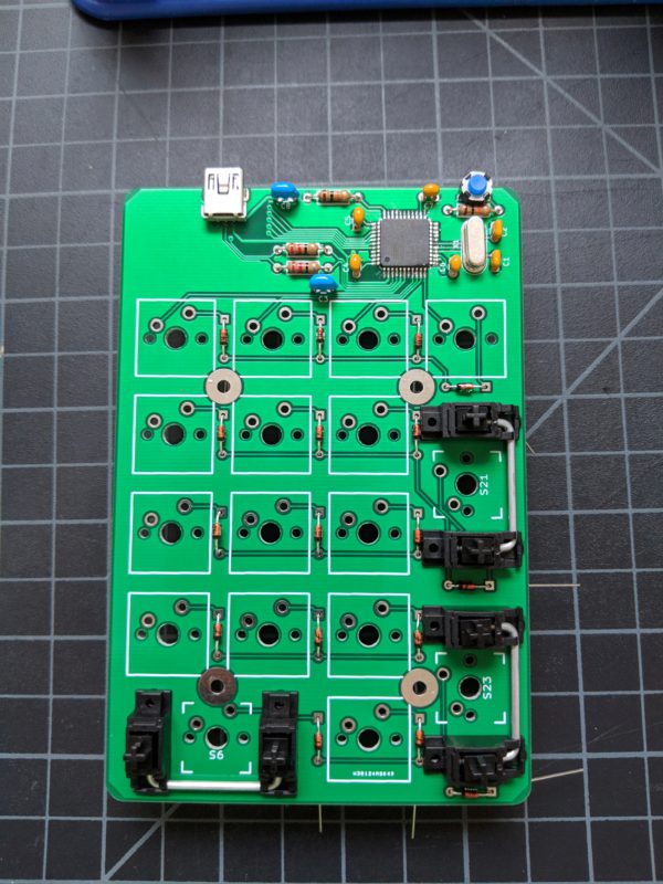
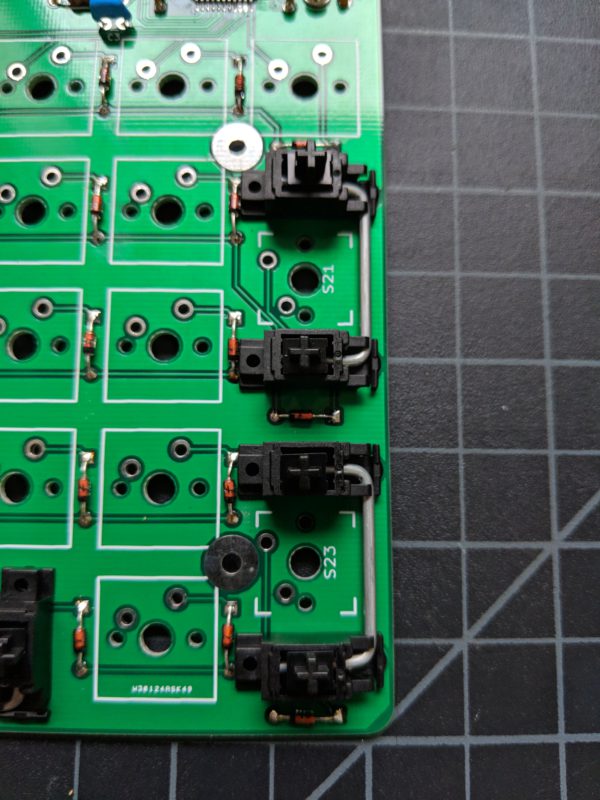
Your stabilizers will either snap or screw into place.
Step 11: Solder switches
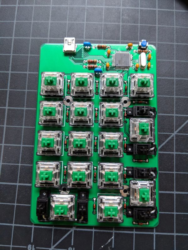
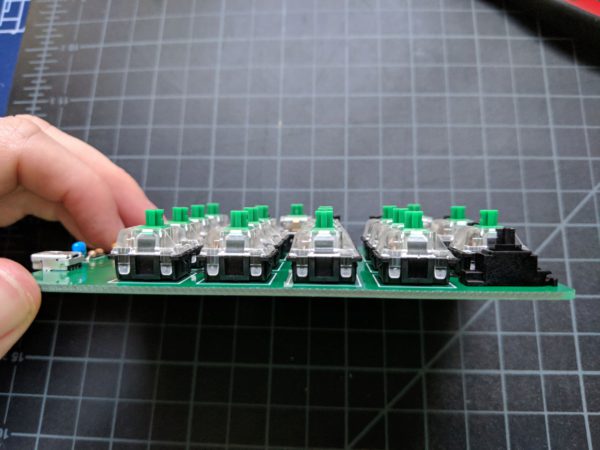
Place your switches on your keyboard with the slit facing down. That slit is for LEDs, but the naKey does not support LEDs.
Note: If you are not building with a cKeys kit, you will need to make sure you get PCB mount (5 pin) switches. Kailh switches will not work. The reason for PCB mount is so that the switches sit straight on the PCB despite lacking a top plate.
Step 12: Add rubber bumpons
Our images of sticking on rubber feet have gone missing. Use your imagination as you invision four rubber bumpon feet being placed, one each, in all four corners on the bottom of the PCB. When the PCB is facing backwards, you may need to experiment with the best placement for the top left bumpon. Components may be in your way depending on the size of your rubber bumpon feet.
Completion